PREV | HOME | NEXT
Testchamber Results
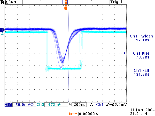
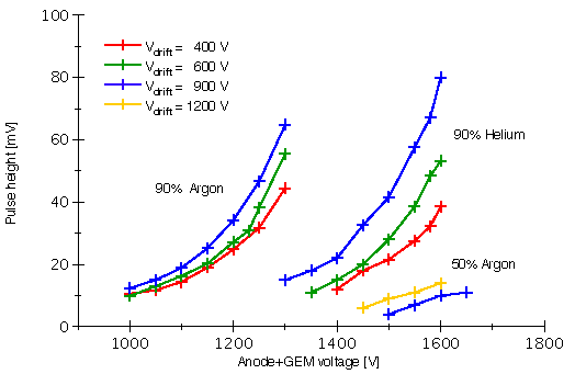
The electronic board is designed to pick up signals from the anode and amplify them to 100 mV pulses, suitable for digitisation. These pulses are then fed to the FlashADCs. The first figure below shows a typical pulse of an amplified GEM signal. The second figure shows the pulse height for different gas mixtures and different drift voltages as a function of the high voltages across the GEM.

